


Structural Characteristics of Automotive Connectors
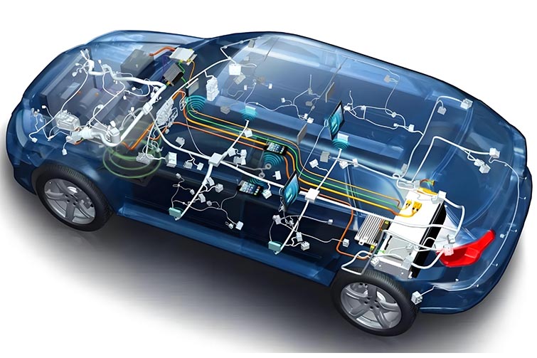
Automotive connectors are precision-engineered components that bear little resemblance to the simple plastic plugs found in household electronics. Their design reflects the extreme demands of the automotive environment: relentless vibration, wide temperature swings, moisture intrusion, and the need for absolute reliability over a decade or more of service. Every element of an automotive connector—from the choice of materials to the geometry of its locking mechanisms—serves a specific purpose. Understanding these structural characteristics reveals why these components are among the most carefully engineered parts in a modern vehicle.
1. The Housing: Protection and Precision
The housing, often called the shell or insulator, is the outermost structural component of a connector. It serves three primary functions: providing mechanical protection, ensuring proper alignment of terminals, and electrically isolating contacts from each other and from the surrounding environment.
Material Selection: Automotive connector housings are almost exclusively molded from high-performance thermoplastics. Common materials include polybutylene terephthalate (PBT) and polyamide (nylon) with glass-fiber reinforcement. These materials offer high dielectric strength, dimensional stability across temperature extremes, and resistance to automotive fluids such as oil, coolant, and fuel. For under-hood applications, materials must withstand continuous operating temperatures up to 150°C while maintaining mechanical integrity.
Keying and Polarization: A critical structural feature is the keying system—asymmetrical features molded into the housing that ensure the connector can only be mated in one orientation. This prevents incorrect assembly that could damage terminals or cause short circuits. In multi-pin connectors, different keying configurations allow visually identical connectors to coexist in the same harness without risk of mismating.
Color Coding: While not strictly structural, color coding is an integral design feature that aids assembly and service. Different colors indicate connector families, pin counts, or application types, reducing the likelihood of installation errors on the production line or in repair shops.
2. Terminals: The Heart of Electrical Conductivity
Terminals are the metal contacts that actually carry current. Their design directly determines the electrical performance and long-term reliability of the connector.
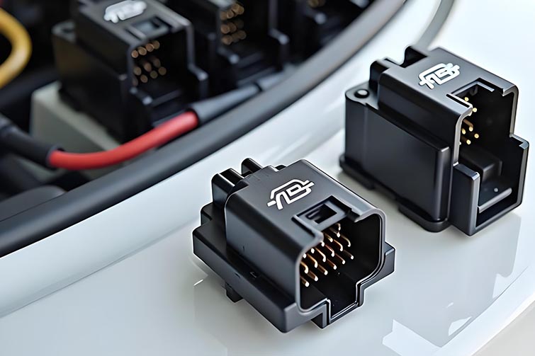
Material and Plating: Terminals are stamped from high-conductivity copper alloys such as brass or phosphor bronze. The base material must balance conductivity with mechanical spring properties, as terminals rely on spring force to maintain contact pressure. Plating is equally critical: tin plating is common for power applications where slight surface oxidation is acceptable, while gold plating is used for low-voltage signal circuits where even milliohms of resistance can cause signal degradation.
Contact Geometry: The interface where two terminals meet is a carefully engineered mechanical joint. Female terminals typically feature a box-shaped design with multiple spring beams that exert consistent force on the male terminal. This multi-point contact design ensures redundant electrical paths and maintains contact pressure even if one beam loses tension. Blade or pin terminals, commonly used in sealed connector systems, provide a robust mating surface resistant to deformation.
Crimp Barrel: The termination point where wire meets terminal is a crimped barrel, not a soldered joint. Crimping provides a gas-tight connection that resists corrosion and withstands vibration better than solder. The crimp barrel is designed with specific geometry to accept a precise wire gauge; using the wrong wire size compromises mechanical retention and electrical conductivity.
3. Sealing Systems: Keeping the Elements Out
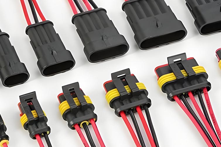
One of the most distinctive structural characteristics of automotive connectors is their elaborate sealing systems. Water ingress is a primary cause of connector failure, and manufacturers employ multiple layers of protection.
Interface Seals: The interface between mating connector halves is sealed with a silicone gasket or individual wire seals. Silicone rubber is the material of choice because it remains flexible across the entire automotive temperature range and compresses reliably without taking a permanent set. Many connectors use a matte seal—a single silicone component with multiple holes through which wires pass—creating a unified barrier against moisture.
Wire Seals: At the rear of the connector, where individual wires enter the housing, small silicone seals surround each wire. These seals are compressed during assembly, creating a watertight barrier around the wire insulation. In unsealed connectors, this area is left open, limiting their application to interior, dry locations.
Cavity Plugs: For unused terminal positions within a connector, cavity plugs (dummy seals) are inserted to maintain the integrity of the sealing system. Without these plugs, moisture could enter through empty cavities and compromise the entire connector.
4. Locking and Assurance Mechanisms
Automotive connectors incorporate multiple mechanical interlocks to prevent accidental disconnection and ensure complete mating.
Primary Lock: The primary lock is the latch or lever that holds the two connector halves together. Most automotive connectors use a cantilever latch that audibly clicks when fully mated. The tactile and audible feedback confirms proper assembly on the production line.
Connector Position Assurance (CPA): A secondary locking feature, the CPA is an additional plastic component that slides or snaps into place after the connector is mated. It physically blocks the primary latch from releasing, ensuring the connector cannot be accidentally unmated by vibration or incidental contact. CPAs are mandatory for safety-critical applications such as airbags, brakes, and engine controls.
Terminal Position Assurance (TPA): Similar to the CPA but applied to individual terminals, the TPA is a plastic insert that locks each terminal into its cavity. It prevents terminals from backing out of the housing due to wire pull or vibration—a failure mode that can cause intermittent electrical contact.
5. High-Voltage and High-Speed Structural Adaptations
As vehicles electrify and adopt high-speed data networks, connector structures have evolved to meet new requirements.
High-Voltage Connectors: For electric and hybrid vehicles, connectors handling 400V to 800V incorporate additional structural elements. Touch-proof designs ensure that no live components are accessible when the connector is unmated. High-voltage interlock (HVIL) circuits use shorting pins that break contact before the main power terminals disconnect, signaling the system to de-energize. These connectors also feature robust shielding to contain electromagnetic interference.
Shielded Connectors: For high-speed data protocols such as Automotive Ethernet, USB, and LVDS for cameras, connectors incorporate metal shielding cans that wrap around the terminals. This shielding provides 360-degree protection against electromagnetic interference, preserving signal integrity in the electrically noisy automotive environment. The shield is grounded through the connector housing, completing the EMI protection path.
Conclusion
The structural characteristics of automotive connectors reflect a design philosophy centered on absolute reliability under extreme conditions. From glass-filled thermoplastic housings with precision keying features, to multi-beam terminals with selective plating, to layered sealing systems and secondary locking mechanisms, every element serves a purpose. High-voltage and high-speed variants add further complexity, incorporating touch-proof designs and EMI shielding. These structural details, often invisible to the casual observer, enable the sophisticated electrical systems that define modern vehicles—and ensure they continue to function reliably for hundreds of thousands of miles.